Jacob Schwartz Scientist & HTML fan
The Princeton Dee magnet
The Princeton Dee is one of the canonical idealized shapes for tokamak toroidal field (TF) magnets. Since increasing the magnetic field is so important for tokamak performance, the TF magnets are subject to extreme engineering: I’ve heard an engineer refer to them as “the most highly structural member ever built”. Energizing the magnet creates an outward $J\times B$ pressure that tries to expand the magnet; this puts the magnet under tension. At every point around the magnet, the tension depends on the local curvature of the magnet shape and the local magnetic field.
The curve of the Princeton Dee shape is somewhat analagous to the catenary formed by a hanging chain: it is an equilibrium shape for carrying currents in a magnetic field that decreases in strength like $1/R$. A wire held in such a shape is in pure tension; there are no ‘bending moments’. The tension is equal everywhere. If we assume a constant width of the magnet’s supporting materials, then, the current can be set such that the tension is maximized everywhere at once. In this manner one can make the most efficient use of structural materials.
This is, of course, an idealization: when building real tokamak coils there are additional forces which are quite important. This includes forces from the poloidal field coils, which try to bend the TF coils out-of-plane, and gravity.
Nevertheless, the shape is still a useful idealization.
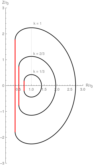
The typical Princeton Dee shape is made of a constant-tension curve of the sort described above as well as a vertical inboard leg, which I show in red. Since the straight portion is no longer following the constant-tension curve, the tension will be different there. On this inner leg of the coil, there is a ‘centering force’ that tries to pull all the TF magnets inward. One way of balancing this force is to build a strong cylindrical ‘plug’ for the tokamak’s center. The flat sides help the magnets rest as much of their length on the plug as possible, thereby decreasing the pressure.
Defining and solving for the magnet shape
The shape is the result of solving a differential equation
\[k r = \left(1 + \left(\frac{dz}{dr}\right)^2\right)^{3/2} \left(\frac{d^2 z}{dr^2}\right)^{-1}\]where $k = (1/2)\log(r_2/r_1)$ and $r_1$, $r_2$ are the desired major radii of the inner and outer legs at the midplane. The three plots I show above are normalized by $r_0 = \sqrt{r_1 r_2}$; they are examples of the shape for different ‘aspect ratios’. From the definitions of $k$ and $r_0$ you can see that the inner and outer legs are at $\exp(-k)$ and $\exp(k)$ in the normalized space. The highest point of the curve is at $R/r_0 = 1$.
New analytic result(?) for enclosed volume
While the equation must be solved numerically to find the $(R, Z)$ coordinates, remarkably, one can find analytical expressions for several important properties of the curve.
The paper by Granick and Tenney gives analytic expressions for the arc length and cross-sectional area of the coils. Here $I_n(k)$ is the modified Bessel function of the first kind.
\[l_\mathrm{turn}/r_0 = 2 \pi k \left(I_0(k) + I_1(k)\right)\] \[A/r_0^2 = 2 \pi k \left(I_1(2k) - \exp(-k)I_1(k)\right)\]The enclosed volume of the coils is of interest because cost estimates are sometimes proprtional to enclosed volume of the coils. Gralnick does not provide an expression for the enclosed volume. I was able to derive the expression below using Mathematica. I’ll leave it as an exercise for the reader: read and understand the paper, especially the derivation for the $A$, and then it’s not hard.
\[V_\mathrm{enc} / r_0^3 = 2 k \pi^2 \left(I_1(3k) - \exp(-2k)I_1(k)\right)\]If you know of this result already in the literature I’d be interested to see where!
Additional analytical expressions reprinted for convenience
Gralnick gives the height of the straight inner leg, \(h/r_0 = 2 \pi k I_1(k),\)
as well as the total height of the coil,
\[h_\mathrm{coil}/r_0 = \pi k \left(I_1(k) + L_{-1}(k)\right),\]where $L_n(k)$ is the modified Struve function. They also provide the inductance of the coil,
\[L/r_0 = 2 \pi k^2 \left(I_0(k) + 2 I_1(k) + I_2(k)\right).\]There probably should be a $\mu_0$ or $4 \pi$ there to convert to SI.
Polar form of the differential equation
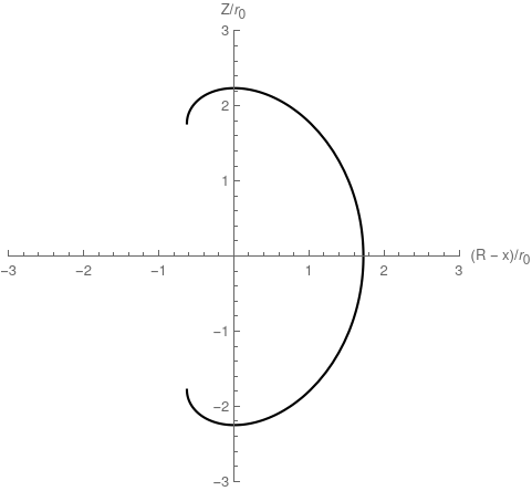
As a slightly different topic, I needed to find the radius $\rho$ of the magnet as a function of angle $\theta$ around the plasma axis.
\[k (\rho \cos (\theta )+x)=\frac{\left(\rho '(\theta )^2+\rho ^2\right)^{3/2}}{2 \rho '(\theta )^2-\rho \rho ''(\theta )+\rho ^2}\]Here, $x$ is a parameter which is a horizontal offset of the polar origin from $R=0$. That is, if $x=r_0$, the crown of the coil will be at $\theta = \pi/2$. The right hand side of the equation is the inverse of the standard expression for curvature in polar coordinates $\kappa(\theta)$. The left hand side is an expression that is proportional to distance from the vertical centerline of the tokamak, with constant of proportionality $k$. Essentially the equation says “curvature is inversely proportional to distance from the centerline”.
References
Gralnick, S. L.; Tenney, F. H. Analytic Solutions for Constant‐tension Coil Shapes. J. Appl. Phys. 1976, 47, 7. https://doi.org/10.1063/1.322993.
This paper is also freely available as a PPPL report.
File, J.; Mills, R. G.; Sheffield, G. V. Large Superconducting Magnet Designs for Fusion Reactors. IEEE Transactions on Nuclear Science 1971, 18 (4), 277–282. https://doi.org/10.1109/TNS.1971.4326354
I think this paper is the first description of the Princeton D shape.
File, J.; Sheffield., G. V. A Large Superconducting Magnet for Fusion Research; MATT-927; Princeton Plasma Physics Laboratory: Princeton, NJ, 1972. https://www.osti.gov/biblio/5839625-large-superconducting-magnet-fusion-research
This similarly-titled, but different, report describes what the shape of the magnets should be when there are only a finite number of coils.
Written on February 28th, 2021