Jacob Schwartz Scientist & HTML fan
Scaling of relative neutron fluxes at inboard and outboard midplane with aspect ratio
The most intense neutron flux in a tokamak is normally found at the midplane. The flux on the inboard side is often a critical value, since inboard space is scarce. The magnets need to be shielded so that they remain operational for the lifetime of the machine, but extra shielding thickness is wasted space.
If we want to optimize a tokamak reactor design, we need a way to estimate the neutron flux at the inboard and outboard midplane. We can use an expensive MCNP calculation to check a few point designs, but it would be useful to have an easy-to-compute relation that gives the relative scaling as a function of the radius of the inner wall, the plasma major radius, and the radius of the outboard wall.
We make a number of simplifying assumptions for this calculation, in order to make the problem tractable. Caution: I am not an expert on neutronics so these assumptions could well be so bad as to make the answer worthless.
- The neutron source has the shape of an infinitestimal ring.
- Neutrons travel in straight lines and do not bounce out of the wall; we are concerned with the fluxes of neutrons ‘initially’ encountering the wall.
The first assumption increases the neutron fluxes somewhat; in reality the source is extended vertically, which smears out what would otherwise be peaks of flux intensity at the midplane. I don’t have enough experience with neutron physics to say how the second assumption affects the result.
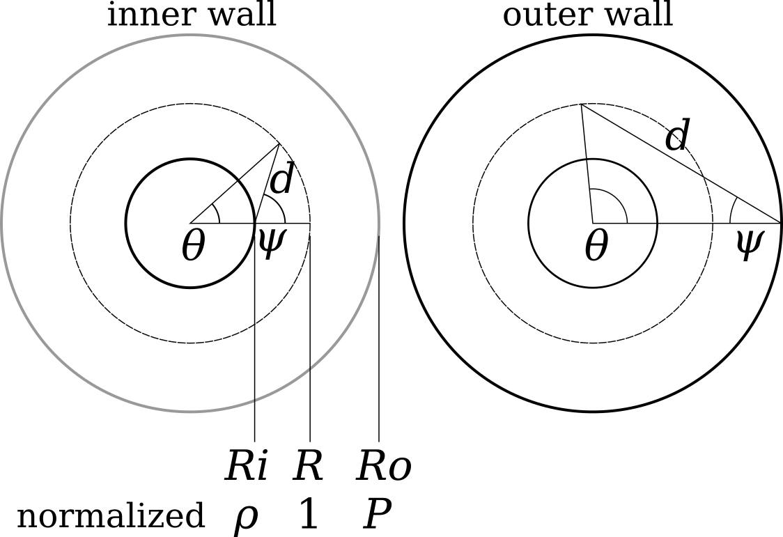
The title image shows the geometry that we’ll use to compute the inner and outer wall fluxes. The inner wall radius is $R_i$, the radius of the neutron source ring is $R$, and the outer wall radius is $R_o$. The angle $\theta$ is the toroidal angle around the tokamak. The angle between the wall’s normal and a location on the neutron source ring is $\psi$. The distance from the wall to a given location on the ring is $d$.
We assume that the neutron source has a strength per unit length $S$. In order to derive a purely geometric factor, we will normalize the results to the flux that the wall would recieve if the geometry were instead a straight tube with radius $a$, namely, $S/(2 \pi a)$. Here $a$ is the minor radius, $R - R_i$.
We will also use a few other geometric normalizations: $\rho \equiv R_i/R < 1$ and $P \equiv R_o/R > 1 $.
Inboard wall flux
The flux on the inboard wall is
\[\Gamma = \int_{-\theta_\mathrm{max}}^{\theta_\mathrm{max}}\cos\psi(\theta) \left(\frac{S}{4 \pi d^2(\theta)} \; R d\theta\right)\]where the term in parenthesis is the flux from an infinetesmal length of the ring source, $S R \; d\theta$, spread over a sphere of area $ 4 \pi d^2$. The $\cos$ term is the angle from a given ray of neutrons to the wall’s normal. The integration is limited to angles $\theta$ that are visible to the wall; too large and the source is ‘below the horizon’.
From elementary trigonometry, $\theta_\mathrm{max} = \arccos(\rho)$, $d^2 = R^2 \left((\cos\theta - \rho)^2 + \sin^2\theta\right)$, and $\cos\psi = (\cos\theta - \rho) / \sqrt{(\cos\theta - \rho)^2 + \sin^2\theta}$. The integral becomes
\[\Gamma = \frac{S}{4 \pi R} \int_{-\theta_\mathrm{max}}^{\theta_\mathrm{max}}\frac{\cos\theta - \rho}{\left((\cos\theta - \rho)^2 + \sin^2\theta\right)^{3/2}} \; d\theta,\]and by normalizing with $\Gamma_n \equiv \Gamma (S/(2{\pi}a))^{-1}$
\[\Gamma_n = \frac{1 - \rho}{2}\int_{-\theta_\mathrm{max}}^{\theta_\mathrm{max}}\frac{\cos\theta - \rho}{\left((\cos\theta - \rho)^2 + \sin^2\theta\right)^{3/2}} \; d\theta\]This integral can be solved using the substitution $u \equiv \cos \theta$, and
\[\begin{split} \Gamma_n = \frac{2 \rho +(1-\rho ) E(\phi_\mathrm{in}/2\,|m_\mathrm{in})-(1+\rho ) F(\phi_\mathrm{in}/2\,|m_\mathrm{in})}{\rho (1+\rho )} \end{split}\]where $\phi_\mathrm{in} = \arccos(\rho)$ and $m_\mathrm{in} = -4\rho/(1-\rho)^2$.
Outboard wall flux
The computation for outboard wall flux is similar except that $\theta_\mathrm{max}$ depends on both $\rho$ and $P$:
\[\theta_\mathrm{max} = \arccos\left(\frac{\rho}{1}\right) + \arccos\left(\frac{\rho}{P}\right)\]The maximum $\theta$ occurs when the source becomes hidden by the center stack. The formula for distance is $d^2 = R^2 (1 + P^2 - 2 P \cos\theta) $ and $\cos(\psi(\theta)) = (P - \cos\theta)/((P - \cos\theta)^2 + \sin^2\theta )$.
\[\Gamma_n = \frac{1 - \rho}{2} \int_{-\theta_\mathrm{max}}^{\theta_\mathrm{max}} \frac{P - \cos\theta}{(1 + P^2 - 2 P \cos\theta)^{3/2}}\; d\theta\]Again, substitute $u = \cos\theta$ and integrate. (This was possible using Rubi’s Mathematica package:
Int[2/(1 + P^2 - 2 P u)^( 3/2) (P - u) 1/Sqrt[1 - u^2], u].)
The result is
where $E$ and $F$ are the elliptic integrals of the second and first kinds, respectively, $\phi = \arccos(\rho) + \arccos(\rho/P)$ and $m = -4 P / (P-1)^2$.
Comparison of the two
We can compare fluxes to the inboard and outboard midplanes. The outboard case has two geometric parameters—the inner and outer minor radii—so we set them equal: that $(R_o - R) = (R - R_i)$, or, $\rho = 1 - 1/A$ and $P = 1 + 1/A$.
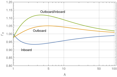
This geometric effect turns out to be relatively small: the two differ at most by about 12%, when $A\approx3.5$. Of course, this has assumed that the source ring is equidistant between the two walls.
As $A \to \infty$ both functions go to 1.
Written on February 6th, 2021